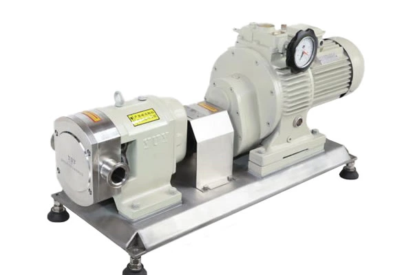
Cip Reflux Pump Troubleshooting
First, make sure that other debris does not enter the pump body.
If solid debris enters the pump body, it will damage the rubber stator of CIP Return Pump, so it is very important to ensure that debris does not enter the pump cavity. Some pumps are equipped with a crusher in front of the pump, and some are equipped with a grille device or filter to prevent debris from entering the CIP return pump. The grille should be cleared in time to avoid blockage.
Second, avoid using the CIP return pump when the material is cut off.
The CIP return pump is never allowed to operate when the material is cut off. Once it happens, the rubber stator will burn out due to dry friction and high temperature in an instant. Therefore, the crusher is intact and the grille is unobstructed. It is one of the necessary conditions for the normal operation of the CIP return pump. For this reason, some CIP return pumps are also equipped with a cut-off shutdown device on the pump body. When the material is cut off, due to the self-priming function of the CIP return pump, a vacuum will be generated in the cavity, and the vacuum device will stop the CIP return pump.
Third, maintain a constant outlet pressure
The CIP return pump is a positive displacement rotary pump. When the outlet is blocked, the pressure will gradually increase to exceed the predetermined pressure value. At this time, the motor load increases sharply. The load of the transmission mechanical related parts will also exceed the design value. In severe cases, the motor will burn out and the transmission parts will break. In order to avoid damage to the CIP return pump, a bypass overflow valve is generally installed at the outlet of the CIP return pump to stabilize the outlet pressure and maintain the normal operation of the pump.
Fourth, reasonable selection of CIP return pump speed
The flow rate of the CIP return pump is linearly related to the speed. Compared with the low-speed CIP return pump, the high-speed CIP return pump can increase the flow rate and head, but the power is significantly increased. The high speed accelerates the wear between the rotor and the stator, which will inevitably cause the CIP return pump to fail prematurely. In addition, the stator and rotor of the high-speed CIP return pump are very short and easy to wear, thus shortening the service life of the CIP return pump.
By reducing the speed through a reducer or a stepless speed regulating mechanism, the speed can be kept within a reasonable range of less than 300 revolutions per minute. Compared with the high-speed CIP return pump, the service life can be extended several times.
Of course, there are many ways to maintain the CIP return pump, which requires us to pay more attention when using it normally. As long as we can observe carefully, we will have a good maintenance of the CIP return pump.
How to deal with the failure of the CIP return pump? This article will mainly introduce the troubleshooting methods of the CIP return pump.
1. The pump body vibrates violently or produces noise:
Cause: The water pump is not installed firmly or the water pump is installed too high; the motor ball bearing is damaged; the water pump main shaft is bent or is not concentric or parallel with the motor main shaft, etc.
Treatment method: Install the water pump steadily or lower the installation height of the water pump; replace the motor ball bearing; correct the bent water pump main shaft or adjust the relative position of the water pump and the motor.
2. Overheating of the drive shaft or motor bearing:
Cause: lack of lubricating oil or bearing rupture, etc.
Treatment method: add lubricating oil or replace bearings. Valve import pump industrial washing machine
3. The water pump does not produce water:
Cause: the pump body and the suction pipe are not filled with water; the dynamic water level is lower than the water pump filter pipe; the suction pipe is broken, etc.
The sealing surface between the screw and the shell is a spatial curved surface. There are non-sealed areas such as ab or de on this curved surface, and many triangular gaps abc and def are formed with the groove part of the screw. These triangular gaps constitute the channel of the liquid, so that the active screw groove A is connected with the grooves B and C on the driven screw. And the grooves B and C go around to the back along their own spirals and are connected with the grooves D and E on the back respectively. Since there are triangular gaps a'b'c' similar to the front on the sealing surface where the grooves D and E are connected with the groove F (which belongs to the other end spiral), D, F, and E will also be connected. In this way, the grooves ABCDEA form an "∞"-shaped sealing space (if a single-start thread is used, the groove will axially wrap around the screw, penetrate the suction and discharge ports, and cannot form a seal). It is not difficult to imagine that on such a screw, many independent "∞"-shaped sealing spaces will be formed, and the axial length occupied by each sealing space is exactly equal to the lead t of the cumulative rod. Therefore, in order to separate the suction and discharge ports of the screw, the length of the screw thread section must be at least greater than one lead.
